P&ID and Smart Schematics

P&ID and Smart Schematics

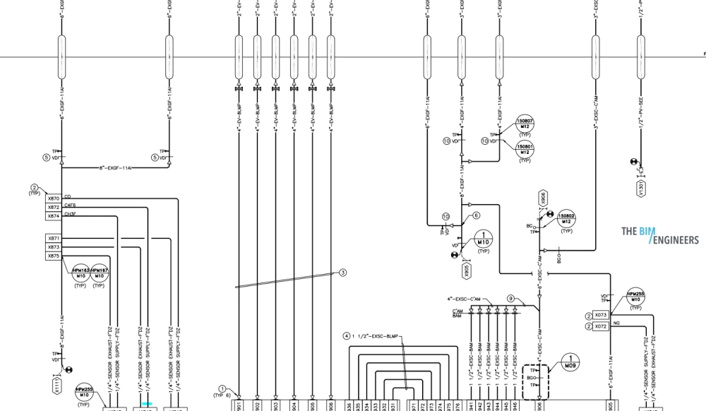
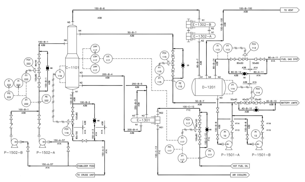
Use of Piping and Instrumentation Diagrams: P&IDs are a schematic demonstration of any functional relationship of piping, instruments, and system equipment components used in the field of Industry or automation.

TBE has a big team of Engineers who design a manufacturing process for the physical plants. Our team follows systematic steps that are mapped out with P&ID to construct a plant design maintaining the safety standards

P&IDs Schematic Representation includes:

Mechanical Equipment with naming and numbering
Valve with identifications
Process piping with sizes and identifications
Vents, Drains, Fittings, Sampling Lines, Swagers, etc.
Flow Directions
Equipment Ratings
Control Inputs and Outputs

Role of P&IDs in Engineering

  • Evaluate Construction Processes
  • Serve as a base for control programming
  • Develop guidelines and standards
  • Create process work documents
  • Provide one language for plant operations
  • Design conceptual layouts of plants
Related Services

Design Validation

BIM Design Validation is a process of pre-check the model informative content required through the rule-set, to valid...

Structural Analysis

An approach used to analyse the behaviour of a given structural system using analytical modelling tools and the BIM d...

Constructability Review

Constructability Review is a process of infusing construction knowledge into the design process during BIM project cy...

Builders Work & Hanger Drawings

The BIM Engineers provide Builders Works/Block Out drawings with high-quality details.

We provide Block Out d...